ref : https://www.facebook.com/bhumisiam/posts/1306029162776539:0
สวัสดีครับแฟนเพจที่รักทุกๆ ท่าน
วันนี้ผมจะมาขอยก ตย ความรู้พื้นฐานที่เราควรจะทราบที่มาที่ไปของสมการที่เราใช้งานกันบ่อยๆ แต่อาจจะหลงลืมไปกันไปบ้างต่อนะครับ
หลังจากเมื่อ 2 วันที่ผ่านมาผมยก ตย ถึงสมการทางด้านกลศาสตร์ของวัสดุไปบ้างแล้ว วันนี้ผมจะขอยก ตย ถึงสมการทางด้านการออกแบบบ้างนะครับ
สมการที่เกี่ยวข้องกับงานออกแบบที่ผมต้องการจะหยิบยกมาในวันนี้เกี่ยวข้องกับการออกแบบหน้าตัดโครงสร้าง คสล ที่ต้องรับแรงดัดโดยวิธีหน่วยแรงใช้งานนะครับ
เราอาจคุ้นเคยกันดีถึงสมการเหล่านี้
k = 1/( 1 + fs / n fc ) (1)
j = 1 – k / 3 (2)
Mc = 1/2 fc j k b d^(2) (3)
As = M / fs j d (4)
ผมก็เชื่อเหลือเกินว่าหากสอบถามเพื่อนๆ ถึงที่มาของสมการเหล่านี้ เพื่อนๆ บางคนอาจตอบได้นะครับ แต่โดยมากก็อาจจะตอบผมไม่ได้ว่าวิธีและกระบวนการในการหาสมการเหล่านี้นั้นมีที่มาที่ไปอย่างไร วันนี้เราจะมาทบทวนกันดูนะครับ
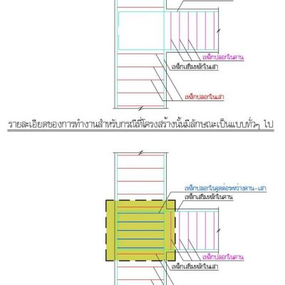
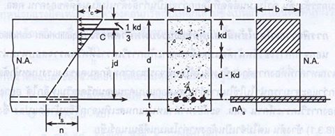
ดูรูปที่แนบมานะครับ พิจารณารูปย่อยทางด้านซ้ายมือสุดนะครับ คานเป็นแบบช่วงเดียว วางอยู่บนฐานที่เป็นจุดหมุนทั้งสองข้าง เนื่องจากคานนี้ต้องรับ นน บรรทุกที่กระทำบนคานจึงทำให้เกิดแรงภายในที่เป็นค่าโมเมนต์ขึ้นในคานมีค่าเท่ากับ M โดยจะดัดทำให้คานแอ่นตัวลง หรือ ที่เราเรียกว่าการดัดแบบโมเมนต์มีค่าเป็นบวกกระทำบนหน้าตัดของคาน ในการที่หน้าตัดนี้จะสมดุลได้จำเป็นจะต้องมีแรงภายในที่ต้านทานต่อค่าโมเมนต์บวก หรือค่า M นี้ นั่นก็คือแรงอัดหรือแรง C ที่ผิวด้านบนของคานและแรงดึง T ที่ผิวด้านล่างของคาน โดยที่ระยะห่างระหว่างแรง C และ T นั้นเราจะให้มีค่าเท่ากับระยะ j d เมื่อค่า d คือความความลึกประสิทธิผลของหน้าตัด หรือ คือระยะห่างระหว่างผิวที่รับหน่วยแรงอัดสูงสุดไปจนถึงเซ็นทรอยด์ของเหล็กเสริมนั่นเอง โดยที่หน้าตัดนี้เป็นรูปสี่เหลี่ยมผืนผ้าความกว้างเท่ากับ b ดังนั้นการกระจายตัวของหน่วยแรงอัดในคอนกรีตจะกระทำเป็นรูปทรงสามเหลี่ยม เราจะให้ฐานของสามเหลี่ยมนี้มีค่าเท่ากับระยะ k d ดังนั้นแรง C จะกระทำผ่านเซ็นทรอยด์ของรูปสามเหลี่ยมนี้ คือ k d / 3 วัดจากผิวด้านบนสุดของคาน ดังนั้นเราจะทราบว่าค่าโมเมนต์จะมีค่าเท่ากับแรงคูณกับแขนของแรง หรือ เท่ากับ
M = C j d = T j d
โดยหากเราพิจารณาในสภาวะที่ยังเป็นเชิงเส้นอยู่ เมื่อค่าหน่วยการหดตัว εc ของคอนกรีต และ หน่วยการยืดตัว εs ของเหล็ก เราจะอาศัยหลักการทางด้านกลศาสตร์ที่ว่าค่าหน่วยแรงสูงสุดของวัสดุใดๆ จะมีค่าเท่ากับหน่วยการยืดหรือหดตัวของวัสดุนั้นๆ คูณกับค่าโมดูลัสยืดหยุ่นของวัสดุนั้นๆ หรือค่า f = ε E ดังนั้น
fc = εc Ec
และ
fs = εs Es
หากเราใช้หลักการของสามเหลี่ยมคล้ายเราจะสามารถสร้างความสัมพันธ์ได้ว่า
εc/εs = (fc/Ec)/(Es/fs) = fc Es / fs Ec
หากค่า n คือค่า MODULAR RATIO = Es/Ec ดังนั้น
n fc / fs = kd / (d – kd)
จะเห็นได้ว่าเราสามารถดึง d ซึ่งเป็นตัวร่วมออกได้ สมการข้างต้นจะกลายเป็น
n fc / fs = k / ( 1 – k )
ทำการแก้สมการออกมาจะได้ที่มาของสมการที่ (1) ว่า
k = 1/( 1 + fs / n fc )
เมื่อเราทราบว่าแขนของแรง C และ T มีค่าเท่ากับ jd และตำแหน่งของแรง C จะกระทำผ่านเซ็นทรอยด์ของรูปสามเหลี่ยมเท่ากับระยะ k d / 3 ดังนั้น
jd = d – kd/3
จะสังเหตเห็นได้ว่าเราสามารถดึง d ซึ่งเป็นตัวร่วมออกได้ สมการข้างต้นจึงกลายเป็นที่มาของสมการที่ (2)
j = 1 – k /3
ต่อมาหากเราต้องการจะคำนวณหาแรง C เราก็สามารถคำนวณ พท ของหน่วยแรงในคอนกรีตได้ว่า
C = 1/2 x สูง x ฐาน x ความกว้าง = 1/2 fc kd b
เมื่อคูณค่า C เข้ากับแขนของแรง jd จะได้ค่าโมเมนต์สูงสุดที่คอนกรีตสามารถจะรับได้ ซึ่งเป็นที่มาของสมการที่ (3) ว่า
Mc = 1/2 fc j k b d^(2)
ในอีกทางหนึ่งหากเราต้องการจะคำนวณหาแรง T เราก็สมารถคำนวณได้ง่ายๆ จาก พท ของเหล็กเสริมคูณกับหน่วยแรงของเหล็กเสริมได้ว่า
T = As fs
เมื่อคูณค่า T เข้ากับแขนของแรง jd จะได้ค่าโมเมนต์สูงสุดที่เหล็กสมารถจะสามารถรับได้ว่า
Ms = As fs j d
ดังนั้นหากเราแทนค่า Ms ด้วย M ใดๆ เราก็จะสามารถหาค่า พท หน้าตัดของเหล็กเสริมได้จากสมการๆ นี้ซึ่งท้ายที่สุดแล้วก็จะเป็นที่มาของสมการที่ (4) ว่า
As = M / fs j d
โอกาสหน้าผมจะมาอธิบายต่อนะครับว่าเหตุใดเราจึงควรม่ีความเข้าใจถึงที่มาที่ไปของสมการเหล่านี้
Let’s continue with an example of basic theory that you frequently use, but you also might forgot that how these equations was develop.
Continuing from the past 2 days I already introduce you about the equations related to structural mechanics. Today I want to show you another example about equations related to structural design.
The equations I demonstrate today is about the design of a reinforced concrete beam section by the working stress design method.
I think you guys might already be familiar with the following equations
k = 1/( 1 + fs / n fc ) (1)
j = 1 – k / 3 (2)
Mc = 1/2 fc j k b d^(2) (3)
As = M / fs j d (4)
I truly believe that if I ask you about how was the above equations derive from many of you can easily give me an answer, but some of you might not. Never mind today let’s revise these equations together with me.
See the attached figure starting from the sub-figure on the left hand side. The beam is a simply supported beam. The both sides of the beam is placed on a hinged support, and the beam has to carry a distributed load above it. Due to this load causes an internal force called moment of M which will bent the beam in the downward directions or what we normally call this type of moment as a positive moment on the beam section. To make this beam to be in an equilibrium stage there must be an internal couple force to balance this load. That is the force C at the top fiber and T at the bottom fiber multiply by a lever arm between these two forces equal to j d when the d is the value of effective depth of section or the distance from the position of the maximum compression stress to the centroid of the reinforced steels. Since the section is a rectangular section with the width equal to b. Hence, the compression stress distribution of the concrete will be in a linear form or a triangular shape. We let the base of this triangle equal to k d, so the C will be subjecting to the centroid of this triangle or equal to k d / 3 from the above side of the beam. From this we now know that the moment will be equal to the force multiply by the lever arm or equal to:
M = C j d = T j d
If the stage we are talking about is the linear stage. When the compressive strain in the concrete will be equal to εc, and the tensile strain in the reinforced steel will be equal to εs. We can obtain the stress using the basis of structural mechanics that the maximum stress will be equal to the strain multiply by the elastic modulus of the considered material or f = ε E so:
fc = εc Ec
and
fs = εs Es
If you apply the concept of similar shape of a triangle we can make a relationship among the values of:
εc/εs = (fc/Ec)/(Es/fs) = fc Es / fs Ec
If the n value is the modular ratio = Es/Ec so
n fc / fs = kd / (d – kd)
We can see that the value of d could be took off. The above equation will be transformed to:
n fc / fs = k / ( 1 – k )
Solving the above equations now yields the equation (1):
k = 1/( 1 + fs / n fc )
Since we knew that the lever arm of the force C and T is equal to jd and the position of force C is at the centroid of the triangle which will be equal to k d / 3, so:
jd = d – kd/3
We can again see that the value of d could be took off. The above expression will now become equation (2):
j = 1 – k /3
If we want to compute the force C. We can easily compute it from the area of the compressive working stress in the concrete equal to:
C = 1/2 x H x S x B = 1/2 fc kd b
When we multiply the value of C with the lever arm jd we now receive the maximum moment that will be produced by the concrete which is also equal to equation (3):
Mc = 1/2 fc j k b d^(2)
In the other hand when we want to compute the force T. We can obtained from it directly by multiplying the cross sectional area of the reinforced steel with the tensile working stress in the reinforced steel equals to:
T = As fs
When we multiply the value of T with the lever arm jd we now find the maximum moment that will be produced by the reinforced steel equal to:
Ms = As fs j d
Hence, if we replace Ms with any value of M. That means that we can now compute the required sectional area of reinforced steel which will finally becomes equation (4) of:
As = M / fs j d
In the next occasion I shall explain further about we need to know about why do we need to know these basis equations.
หวังว่าความรู้เล็กๆ น้อยๆ ที่ผมได้นำมาฝากพี่แขก และ เพื่อนๆ ทุกๆ ท่านในวันนี้จะมีประโยชน์ต่อทุกๆ ท่านไม่มากก็น้อย และ จนกว่าจะพบกันใหม่นะครับ
ADMIN JAMES DEAN
BSP-Bhumisiam
เสาเข็ม สปันไมโครไพล์ ช่วยแก้ปัญหาได้เพราะ
1) สามารถทำงานในที่แคบได้
2) ไม่ก่อให้เกิดมลภาวะทางเสียง
3) หน้างานสะอาด ไม่มีดินโคลน
4) สามารถรับน้ำหนักได้ 20-40 ตัน/ต้น
5) สามารถตอกชิดผนังกำแพง ไม่ทำให้โครงสร้างเดิมเสียหาย
สนใจติดต่อสินค้า เสาเข็ม ไมโครไพล์ (Micropile) สปันไมโครไพล์ (Spun MicroPile) มาตรฐาน มอก. ของ ภูมิสยาม ซัพพลาย ติดต่อ สายด่วน โทร 081-634-6586